3D opportunity for scan, design, and analyze has been saved

3D opportunity for scan, design, and analyze The first phase of the digital thread
02 November 2016
The digital thread is a single, seamless strand that carries data through the additive manufacturing (AM) process. Reaping the benefits of AM requires an in-depth understanding of the digital thread—including the first phase, scan/design + analyze, which lays the groundwork for subsequent stages.
Understanding the digital thread: An overview
Additive manufacturing (AM) technology has made dramatic strides in recent years in advancing the role of digitally based, remotely connected production processes. Despite these advances, however, AM is still largely a solution that is used for rapid prototyping and small-batch production. Large-scale mass production is not as common because of the inherent difference between AM and traditional manufacturing processes. Whereas traditional subtractive manufacturing is largely a physical series of steps in one location, the AM process draws upon a digital design file to deposit material, layer upon layer, to construct three-dimensional (3D) printed parts composed of often complex geometries. For AM processes to scale at the industrial level, a series of complex, connected, and data-driven events need to occur. We refer to this series of data-driven events as the digital thread.1
Learn More
Register for our upcoming course
In 3D opportunity and the digital thread: Additive manufacturing ties it all together, we discussed the importance of the digital thread as well as some of the challenges that practitioners have in leveraging it to achieve AM solutions at the enterprise level.2 But the integrity of the digital thread is only as good as the strength of its constituent parts. As such, any in-depth understanding of the digital thread—and reaping the benefits of the AM process, more generally—must require a thorough understanding of each phase that comprises it.
Any in-depth understanding of the digital thread—and reaping the benefits of the AM process, more generally—must require a thorough understanding of each phase that comprises it.
In this paper, we discuss the first phase of the digital thread: scan/design + analyze (SDA). In so doing, we will:
- Define each step in the SDA phase by outlining the activities performed
- Discuss key considerations and enablers of the digital thread in each step within the phase, describing factors and challenges to consider when setting up and executing each step in the SDA phase
- Review a real-world example that illustrates each step in the SDA phase
Drawing on the larger, more complete map of the digital thread, we will examine these crucial first stages of the process. As the initiation of the digital thread, SDA lays the groundwork for subsequent stages. Thus, it is crucial to examine the steps and considerations that enable the creation of an accurate design file to drive production.
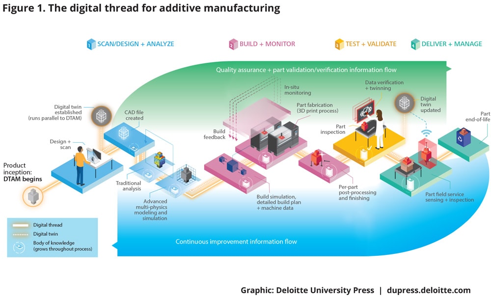
The digital thread for additive manufacturing (DTAM) is the backbone that carries the information through the AM process. Specifically, the DTAM is a single, seamless strand of data that stretches all the way from the initial design concept to the finished part, constituting the information that enables the design, modeling, production, validation, use, and monitoring of a manufactured part.3
As an individual object is designed, tested, produced, and used, it is described by data created throughout the DTAM. The ability to dissect, understand, store, and utilize these data, as well as to manage intense computing demands, allows innovators to scale AM production, manage the complexities of AM, and connect AM across the supply chain. Figure 1 depicts the DTAM.
Scan/design + analyze: Creating the object
Scan/design + analyze occurs at the start of the DTAM as it marks the product’s inception, and occurs firmly in the digital realm. During this stage, designers build 3D models using computer-aided design (CAD) tools or by 3D scanning. With computational analysis, these models can be revised to optimize design prior to production, potentially saving physical waste, time, and money.
SDA consists of three subphases:
- Scan: Converting an existing object into a digital file
- Design: Manipulating the scan or designing a wholly new object
- Analyze: Creating a feedback loop for effective design
We will now focus on each of these subphases.
Scan: Converting an existing object into a digital file
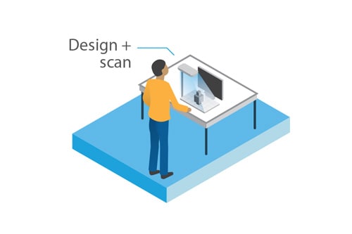
The scan step is conducted when there is a preexisting physical object to be duplicated and/or modified. During this step, the designer translates the physical part into a digital representation of itself. This step not only establishes the model-based style pervasive to the DTAM but also marks the beginning of the digital twin: a parallel, digital embodiment of all design, production, quality, and field-use data associated with the part.4
The scan step is conducted when there is a preexisting physical object to be duplicated and/or modified. During this step, the designer translates the physical part into a digital representation of itself.
The scan step utilizes 3D scanning equipment that facilitates the collection of data describing existing structures with dimensions. For example, the object in question must be able to function within the larger structure or ecosystem in which it operates. Thus, its dimensionality and unique characteristics must be accurately captured and depicted within the digital program. To that end, scanners produce “point clouds”—essentially points in space, as with an X, Y, Z coordinate system—where the surfaces of the structures exist.5
Considerations for the scan step
Specific considerations for the scan step include software and software compatibility (proprietary vs. nonproprietary), scanning equipment, image resolution, and data integrity. Each is described below.
Software and software compatibility. Objects can be designed using 3D scanning data as inputs to a CAD software model. Three-dimensional scanners have the ability to produce dimensional data for both proprietary and nonproprietary (that is, open source) software. Proprietary software is designed for the specific needs of an organization and works only within a given operating environment. Nonproprietary software is developed by a community of volunteers often paid by other organizations and can be free or relatively low cost.6 There are advantages and disadvantages to each, described below, that an organization must consider when determining whether to use one or the other or a combination of both.
Proprietary software may be advantageous when moving data from one step in the process to the next because it can be designed with the organization’s specific security requirements and organizational needs in mind. However, this is more expensive and can lock an organization into a single proprietary solution. It may not be practical for companies to exchange product and manufacturing information with many suppliers and customers.7 This may require the organization to invest in proprietary software across the entire digital thread to include the software of vendors, suppliers, customers, and other stakeholders, adding to the price tag.
Compatibility issues can also arise with proprietary software, creating challenges of interoperability between steps of SDA or phases of the DTAM. This is an important consideration for organizations interested in connecting the digital thread across multiple process steps and geographic locations. It may grow even more challenging as the number of vendors, suppliers, and other organizations become part of the digital thread, each potentially using different software.
Nonproprietary software likewise has pros and cons. Open source software tends to be lower cost, more customizable, nimble, open to integration, and more responsive to bug and security fixes.8 On the other hand, open source software often does not have specific responsibility assigned to it. There is no company or direct customer service an organization can contact for issues that arise. Open source software is also not aligned with specific corporate or organizational needs.9
There is no single right answer as to whether to use proprietary or open source software. Organizations must carefully consider their goals, objectives, and requirements for developing their DTAM when making software decisions. It is important that this be done before the SDA phase is initiated; all the design data are established there and have cascading effects throughout the rest of the DTAM.
Scanning equipment. Designers digitally capture an object using a 3D scanner. Organizations must select the right scanning equipment for their needs, to ensure the desired accuracy and integrity of the design and object throughout the rest of the DTAM process. The designer will determine the focal point distance and select the appropriate scanner, whether short, mid, or long range. Descriptions of several common types of scanners along with their pros and cons are depicted in table 1.10
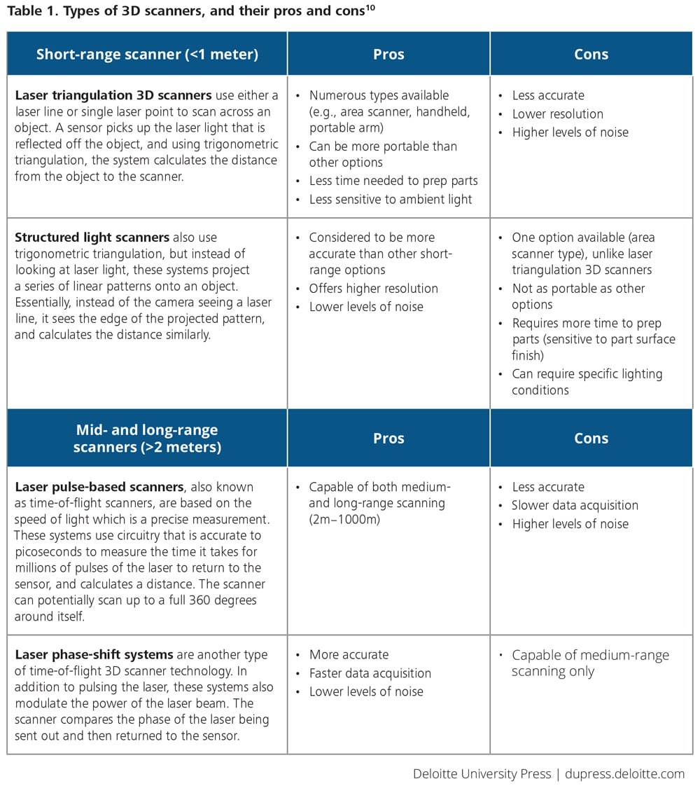
The most appropriate scanning device for a particular job depends on the size, complexity, and material of the object. For example, for larger objects or sites, mid- or long-range scanners may be used. Selection of the appropriate scanning device is critical, as information captured in the scan step can dictate the accuracy of the digital file and, by extension, the final product. An inaccurate or insufficiently detailed scan could conceivably compromise the integrity of the process.
One of the chief concerns to consider when scanning is the quality and accuracy of the image. Image resolution is integral to the production of a functional part; without it, parts can contain insufficient detail or even fail to fulfill their intended purpose.
Image resolution. One of the chief concerns to consider when scanning is the quality and accuracy of the image. Image resolution is integral to the production of a functional part; without it, parts can contain insufficient detail or even fail to fulfill their intended purpose. The quality of an image can be impacted by the following:
- Optically uncooperative materials. If the object has a high polish, for example, it may be more difficult for the scanner to accurately capture the object.11
- Scanning in the presence of occlusions. Depending on the design of the object, any divots, craters, undercuts, or intricate designs may not be captured accurately if the scanner cannot see all areas of the object. In some cases, visibility to all portions of an object may be extremely difficult, if not impossible, to achieve—requiring more work by the designer in the design step. However, advances in scanning technology have improved scanners’ ability to gauge density, measure thickness of the material, and see through occlusions to capture areas behind them.12 It is important to note, however, that scanners cannot capture internal geometries; for that level of detail, additional design is needed.
- Scanning large objects at high resolution: Depending on the size of an object, it may be necessary to scan it multiple times from different angles. Larger objects will likely require more scans than smaller objects for a similar resolution. The more scans an object requires, the greater the likelihood for image distortion. The designer will then need to manually adjust the image in the software program. Alternatively, the larger object may be captured in the same number of scans but would require a further focal point distance. As discussed in table 1, mid- to long-range focal point distances sacrifice resolution and introduce more noise. As a result, the risk of image distortion increases.13
- Accurate scanning in the field: Field conditions can be difficult or impossible to predict, and can be impacted by a variety of factors: scanner calibration, lighting inconsistencies, the state of the object itself, and consistent scanning for the same part at different geolocations, among others.14
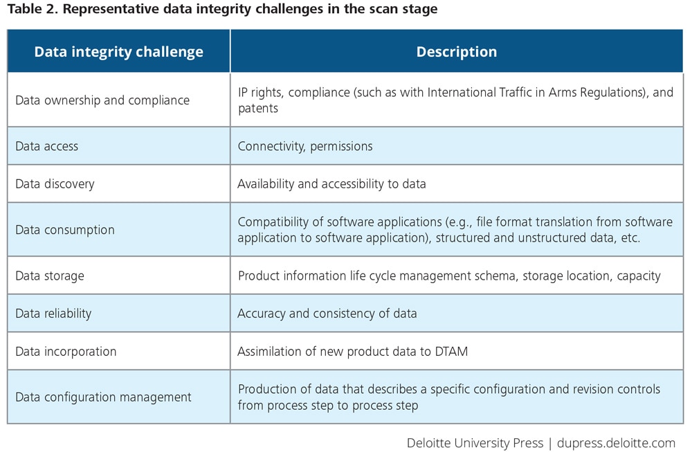
Data integrity. Data underpin the entirety of the DTAM; an inability to ensure data accuracy and security can impact the integrity of the process itself. Depending on the level of quality assurance and the scale of production required for the part, collecting, deciphering, verifying, and securing the scan data can be a daunting task. Data integrity challenges are manifold and must be considered prior to and after scanning. We outline a few of these challenges in table 2.
While the scan step is not always executed as part of a digital thread, when it is, it is essential that it is done correctly. That means that it is essential that the practitioner make the right choice in scanner type considering the need as well as the challenges that affect the scanning process and subsequent steps. Scanning of a physical object is just the start of the story. Once the scan takes place and the image is in a computer model, further processing occurs in the design step.

Design: Manipulating the scan or designing a wholly new object
During design, ideas are transformed into 3D computer models using CAD tools.15 Digital design generally follows the design process outlined in figure 2 to capture details of design in a digital format.
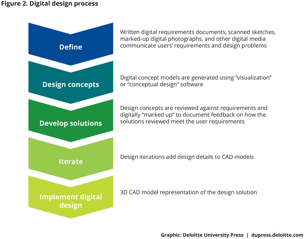
The 3D computer model resulting from the design step serves as a set of instructions—or blueprints—that the AM equipment will use to produce the physical object.
There are some instances, however, in which a scan may contribute to the design process even when designers are creating a new object.
The design stage can occur either directly after scan, or in place of it when a wholly new object is created for which no scans exist. There are some instances, however, in which a scan may contribute to the design process even when designers are creating a new object. For example, a part being designed may need to fit onto an existing physical system where mounting holes currently exist. In this scenario, the CAD designer could engineer the new part to the dimensions of the physical mounting location provided in the scan step output files. In this way, designers may use outputs from the scan step as a means of progressing their design development.
In other scenarios, however, the design stage may proceed without scan. These include situations in which an object is being created without the benefit of an existing physical part, template, prototype, or surrounding area in which the part must fit in or affix to a surrounding fixture. Another example is where the object is a new design where there is no physical object or assembly from which design features can be copied or used to speed up the design of the new object. In these cases, the designer will create the digital version of the object directly, using design software.
Considerations for the design step
Specific considerations for the design step include design and slicing software, interoperability between AM steps, use rights, and maintaining traceability from physical object to scan data to CAD model. Each is described below.
Design and slicing software. Design and slicing software serves as the foundation of any AM process. Thanks to a flurry of product development activity, software choices abound. Recent work in this area includes the development of cloud-based CAD design software that promotes remote collaboration, as well as developments in software that increasingly improve the color and textural granularity of an object.16 Other research has focused on the quality assurance verification ensuring what the designer created digitally corresponds precisely with the dimensionality of the end object.17 Regardless, design software still continues to evolve, and may be edging close to helping companies realize the full potential of AM. (See the sidebar “Topology optimization.”)
Yet, with progress come challenges. As design software becomes more complex and multifaceted, programmers and designers will need additional training and experience. And, of course, as software development continues, the ways in which designers and other AM professionals interact will also evolve, requiring forethought on the part of organizations.18
Topology optimization
Topology optimization is the use of computational analysis to algorithmically optimize design. These techniques often generate designs that cannot be manufactured by traditional subtractive techniques.19 Topology optimization algorithms allow designers to apply constraints directly to the CAD model, finding an optimized design solution, such as lightweighting of parts, while enhancing performance. This process is noteworthy, as it creates multiple benefits for designers and represents a key enabler of AM—and a key result of a holistic digital thread. In the future, topology optimization may become a crucial part of a fully robust DTAM.
Increasingly, engineers are able to harness topology optimization directly because of the design complexity allowed by AM. Although topology optimization solutions have been developed in the past, only recently with the development of AM has the ability to manufacture such designs been possible.
Design optimization leads to significant downstream cost savings for manufacturers in scrap materials and increased design efficiency.20 Researchers are also examining optimizing support material use, which would lead to further reduction in scrap rates.21
Research into AM-specific topology optimization is maturing rapidly. A key research topic is the inclusion of rules around design for manufacturability in the optimization process, such as limitations on internal voids and overhang constraints.22 Topology optimization gaps include the inability to account for anisotropy, or directional dependence, created in the manufacturing process as well as the inability to optimize build orientation for part strength.23
Topology optimization and AM are codependent: AM enables algorithmically optimized design, while designers will look heavily toward AM as the power of topology optimization algorithms increases.
Interoperability, both between AM steps and CAD tools. Consideration can be given to how tools used in the design step interoperate with the outputs from the scan step, as well as with the various tools used in the analyze step. While use of standards, such as ISO STEP AP 242 for managing model-based 3D engineering, can help improve interoperability, they only apply when all stakeholders adhere to the same approach. File interoperability between steps is vital in bringing the physical part or environment into the digital realm. Tests of file interoperability between tools used within an AM process step should be conducted to ensure the successful migration of data between the tools and to check reliability of the data interoperability prior to making a financial investment.24
Additionally, CAD tool interoperability presents a notable consideration for designers and engineers. Exchanging files across design platforms used in the design step or between multiple CAD tools has historically been at the root of many design challenges.25 CAD tools can struggle to convert one native CAD file format to another one. 26 Issues can range from the loss of dimension data within the CAD file to “broken” design model representations.27 Practitioners can consider investigating the source tools used by design service providers or by disparate corporate design shops to align design tools selected with those file formats that are supported and/or used by their designers—and, again, the practitioner must test the reliability of file conversion prior to the purchase decision.
Use rights. Input scan data may or may not be subject to patent or intellectual property (IP) rights and use restrictions.28 Practitioners should research and understand how the scan data captured may be controlled or require use rights before including it in a design model. Proactive analysis must be done to avoid pitfalls with AM-related IP. Because AM technology is still young, much of the AM IP landscape has yet to be developed, but a strong way of mitigating IP risk is by striving to create mutually beneficial deals based on an understanding of the economics of AM.29
Practitioners should research and understand how the scan data captured may be controlled or require use rights before including it in a design model.
Maintaining traceability from physical object to scan data to CAD model. Maintaining the traceability of descriptive and physical identification attributes across the scan and design steps is crucial for the integrity of the resulting design computer model. The origin of the scan data may embody important information if, for example, similarly designed parts or systems do not have the same dimensions. Dimensional differences can emerge from production variations or stresses from use, but scan or design data from the original object can contribute to the body of knowledge that can help identify where those variations occurred. These variations can be captured and become part of the information used to document the design variations and aid in engineering analysis. Thus, the variations can be used to establish tolerances integral to the build/monitor phase supporting quality control.
Overall, the success of the end object—and how precisely it achieves the original vision—depends on the integrity of the design step. It is in the design step that the object’s physical properties and contours are initially established. Yet, as important as the design step is within the digital thread, it does not occur in isolation. Rather, the design step is intimately linked to—and ultimately refined by—the iterative analyze step that follows, completing the design process. (See the sidebar “Scan/design + analyze in the real world.”)
As important as the design step is within the digital thread, it does not occur in isolation. Rather, the design step is intimately linked to—and ultimately refined by—the iterative analyze step that follows, completing the design process.
Scan/design + analyze in the real world
The situation: A national defense organization uses a heavy-duty vehicle to move large, heavy equipment and machinery around its maintenance depot in the performance of maintenance on a major weapon system. One of these vehicles suffered a broken tooth on a gear in its engine, which rendered the vehicle unusable. The vehicle is vital to keeping the organization’s maintenance operations moving. The company that makes the gear went out of business long ago, and there was no known source of replacement gears or complete technical and engineering data from which a new gear could be manufactured.
The objective: The organization determined that it would use the existing broken gear to replicate the gear in a digital model, then use the model to produce a prototype gear via AM.
The approach: To begin, a scan was made using a 3D scanner to produce a digital image of the part. An engineer then added engineering design details to the digital image, including tolerances and material type properties, and a good gear tooth was designed into the CAD model to replace the broken gear tooth in the image.
The designer conducted a virtual analysis on the gear design model to determine the manufacturability using AM, and to ensure that the gear design was suitable for form, fit, and function. Several iterations between analysis and design ensued as the design details were improved and finalized.
The outcome: The successful inception of the gear data captured in the scan, design, and analysis steps resulted in good design data, which fed downstream steps in the DTAM. This eventually resulted in the successful additively manufactured replacement part, making the vehicle fully mission capable and restoring normal maintenance depot operations.
Analyze: Creating a feedback loop for effective design
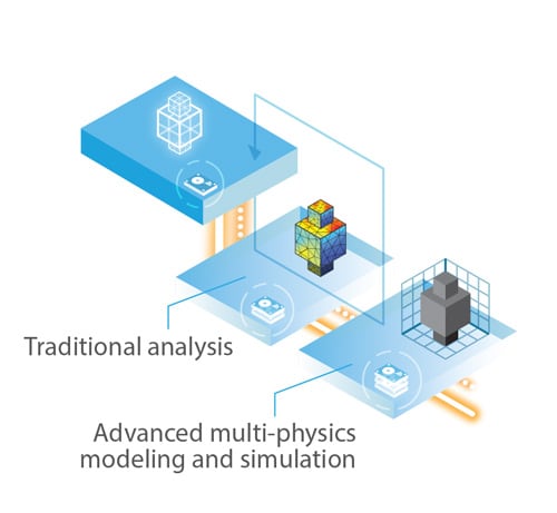
3D scanning and digital design tools are key enablers of the digital thread, and are the first building block of the digital twin. However, these tools do not differ substantially from their use in a subtractive manufacturing environment. The analyze step constitutes the first departure from traditional manufacturing approaches, where traditional design capabilities can be extended and optimized due to the flexibility and complexity of AM.
3D scanning and digital design tools are key enablers of the digital thread, and are the first building block of the digital twin. However, these tools do not differ substantially from their use in a subtractive manufacturing environment.
Analysis begins upon completion of scan and design.30 The design is analyzed to better understand the structural, thermal, material, and fluid flow properties of the part. This enables manufacturers to use the outcomes of tests and modeling to inform design improvements, test again, and continue until functionality is optimized. This process is known as the design-analysis feedback loop.
The basic structure of the design-analysis feedback loop exists for every object and is depicted in figure 3. However, as requirements related to part performance, cost, and life cycle become more stringent, the complexity of the analysis increases. Incorporating these computationally intensive processes into DTAM requires extensive network, storage, and compute infrastructure.
In this section, we will describe how the AM design-analysis feedback loop differs from common digital manufacturing practices, the capabilities that this portion of a DTAM needs to support, and the infrastructure capacity needed to harness those capabilities.
The design-analysis feedback loop
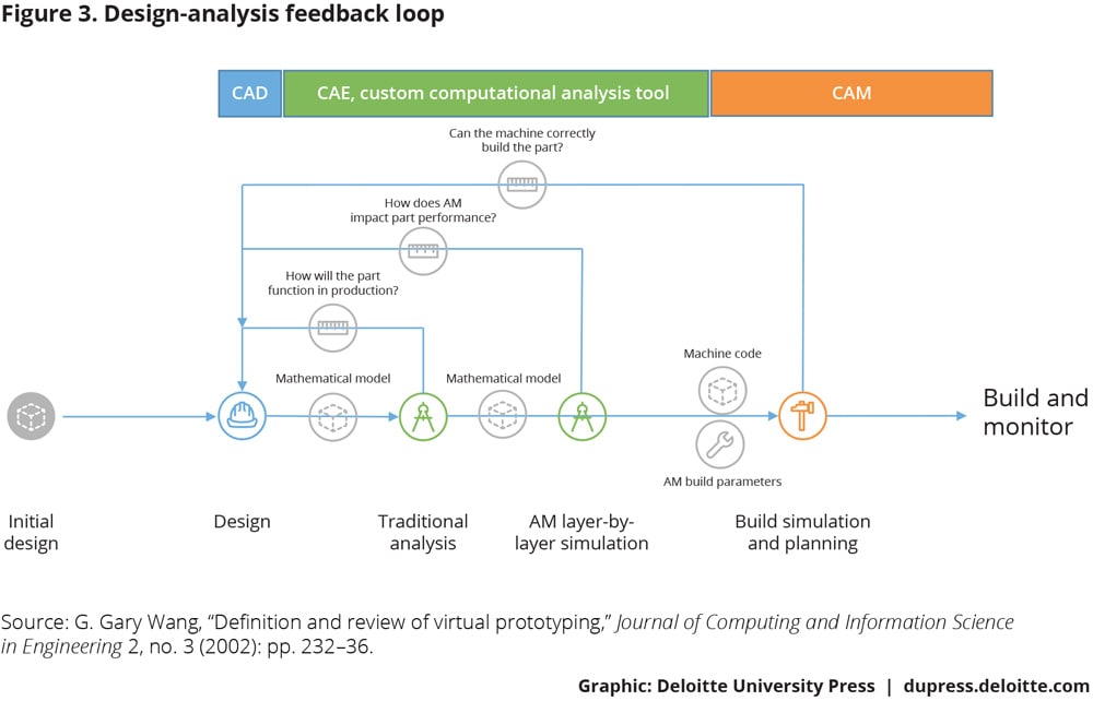
Once the initial design file is created or scan completed, the iterative design-analyze process begins. The design file is imported into a computer-aided engineering (CAE) system. CAE tools provide detailed computational analysis, including the structural, thermal, and fluid dynamic analyses using methods such as finite element analysis and computational fluid dynamics.31 Analysis results are used to iterate part design.
Build simulation and planning run concurrently with computation analysis. Machining processes are simulated, verifying manufacturability. The instruction set is translated into machine code using a computer-aided manufacturing (CAM) platform.32
Digital prototyping for AM. In the case of AM, the build can be simulated layer by layer by multiphysics modeling, creating a holistic model from the microstructure—the composition of the part on an atomic scale—to the assembly level (figure 3). This provides engineers with an analysis of how the build process will impact performance, creating better estimates of part quality and models of part life cycles.33
More importantly, these models can be used to influence the build process. Simulations of the build process develop machine parameters—as many as 130 unique variables—before the part reaches production.34 These parameters are passed into the machine in a process known as feed-forward control, which allows manufacturers the ability to create higher-quality parts with minimized post-production steps.35
Between traditional computation analysis and the AM-build simulations, a body of knowledge is generated that includes insights into material properties,36 performance testing data, and predictive models for purposes of future maintenance scheduling and cost of ownership management.37
Once the process of the design-analysis feedback loop is completed, a revised CAD file is generated and passed onto the next phase of the digital thread for build planning and simulation. During this stage, designers simulate the manufacturing process and verify the manufacturability of the part, which may result in further design iterations.
Based on data generated during the design-analysis feedback loop process, the digital twin running alongside the object contains a history of the design iterations, finalized design files, and engineering analysis of the AM build and part performance. The analysis results fold into the digital twin, providing a detailed picture of how the part is expected to perform in the physical world, and how the part may behave over its life cycle—all before a part reaches production.
Considerations for the analysis step
As manufacturers seek to develop an effective design-analysis feedback loop, they must address many of the challenges of this data-intensive, iterative exercise, and develop IT infrastructure for high-performance computing (HPC) and simulation data management.
Multiphysics modeling. Most computational analysis techniques are designed to address individual types of physical systems. Multiphysics models, however, couple phenomena to create a holistic view of the impact of an event.38 Although commercial analysis packages do include multiphysics capabilities,39 to accurately describe the physics involved in the AM process, custom codes such as ALE3D or TRUCHAS must be used.40 These codes require in-depth expertise in computational mechanics to adapt and apply. Efforts are underway to operationalize these codes for widespread use.41
Converting models across platforms. Computational analysis is conducted on a mathematical model that subdivides a part into a mesh of “finite” geometries.42 Issues may arise while converting from a 3D model to a finite element model for analysis or a tessellated model for manufacturing simulation.43
Commercial CAE platforms offer a wide range of tools for interoperability, such as application-specific interfaces and plug-ins.44 Organizations should account for interoperability of computer-aided technologies (CAx) and product life cycle management (PLM) solutions throughout their supply chains, and define a technical architecture that harnesses the best path from design to build with the least transitions between platforms. This may include understanding data transfer from support providers and subcontractors.
IT infrastructure for HPC. The cost of simulations is directly related to the complexity of the engineering problem. Compute power requirements are substantial, especially as design and analysis complexity increases.45 Low complexity (linear, minimal “degrees of freedom”) may be solved in a matter of minutes on an engineer’s desktop computer with tens of gigabytes of RAM and an off-the-shelf multicore processor.46 While simple simulations can be run on engineering workstations, highly nonlinear, multiphysics, and multiscale simulations require parallel computing on HPC clusters.47 HPC has been a longstanding necessity for the design of high-criticality parts, particularly in aviation.48 Currently, due to complexity and scale, AM build simulations push the limits of HPC capacity, running for days or weeks on hundreds of processor cores.49
The CAx industry is mature, and manufacturers tend toward established offerings. The democratization and commoditization of compute power have yet to reach industrial manufacturing. However, cloud-based CAE and HPC are in development and will offer small- and medium-scale manufacturers the ability to operationalize CAE and HPC tools without capital expenditure from their IT organizations.50
Simulation data management. The outputs of advanced modeling, in terms of data quantity, can be on the order of petabytes or more.51 Simulation data need to be incorporated into a manufacturer’s PLM solution. Simulation data have considerations similar to scan and design data, including compliance, storage, and integrity.
Conclusion: Getting started
As organizations seek to implement a digital thread, it is crucial to understand and plan for the first phase in the process: scan/design + analyze. It is within the SDA phase that the fully realized digital design file is achieved—a step that forms the essential prerequisite of a functional digital thread.
In this paper, we examined the SDA phase and each step within it. In so doing, we placed particular emphasis on the considerations that accompany each step, including the challenges that practitioners must confront and overcome as they seek to accurately execute this phase. While each step entails different technologies and processes, several common considerations emerge that span the entirety of SDA:
- Ensure interoperability. Ensuring systems can interoperate and share information effectively is perhaps the most crucial capability to provide integrity across any stage of the digital thread, as information must flow between stages for the process to function effectively.
- Consider the approach to data management. At its essence, the DTAM is a flow of data from one phase to another—and, in the case of SDA, from one subphase to another. The ability to manage, secure, and store the vast amounts of data that result from a DTAM is crucial to its successful application.
- Invest in the right tools to address specific needs. Depending on the object being produced, different types of scanners, design programs, and computational analyses will need to be employed. A thorough understanding of the range of options for each application can help manufacturers select the tools that best serve their needs.
- Have a plan for talent. Beyond accepting and adopting the digital thread process as a whole, engineers will also need to understand how and when to use the proper scanning, design, and analysis tools and technologies. Training talent on how to do so most effectively will be a crucial part of successfully employing SDA.
The SDA phase is the initial phase within the DTAM. But it is not the only phase, nor is it necessarily the most challenging one. Indeed, all of the DTAM’s phases are comparably challenging, and each plays a unique role in completing the DTAM and achieving AM solutions. Each phase interacts and is inexorably linked with the other parts of the DTAM. Yet it is essential that the practitioner undertake proper design and effective analyses within the SDA phase through a thoughtful, deliberative approach, as this is imperative to the success of the remaining DTAM phases. Such a deliberative approach is as much a requirement with respect to the SDA phase as it is to each and every other phase within the DTAM.
To be sure, DTAM efforts can invoke complex technology integration initiatives and must be managed accordingly. Such complexity is a function of an organization’s strategic intent with regard to AM. But a well-designed DTAM is required as the foundation and information management backbone to enable the realization of a robust AM capability.
© 2021. See Terms of Use for more information.


